
I designed this based off the 3 major wash and cure stations, Anycubic, Elegoo and Prusa. I was looking for a way to do it a bit cheaper, I have a DIY cure box, so just needed the wash. This will spin one direction for half of the cycle, then reverse and finish the cycle. I suppose if you find a big enough wash bucket it could also be used for the larger format resin printers like the Elegoo Saturn. It’s arduino based, I will include the arduino sketch, as dirty as it is, I’m not a coder by any means. Also I will have links to all the files I have created for this project to include Fusion 360 STEP files, STL’s and schematic. I will include a parts list with Amazon links, as well as a download section at the bottom.
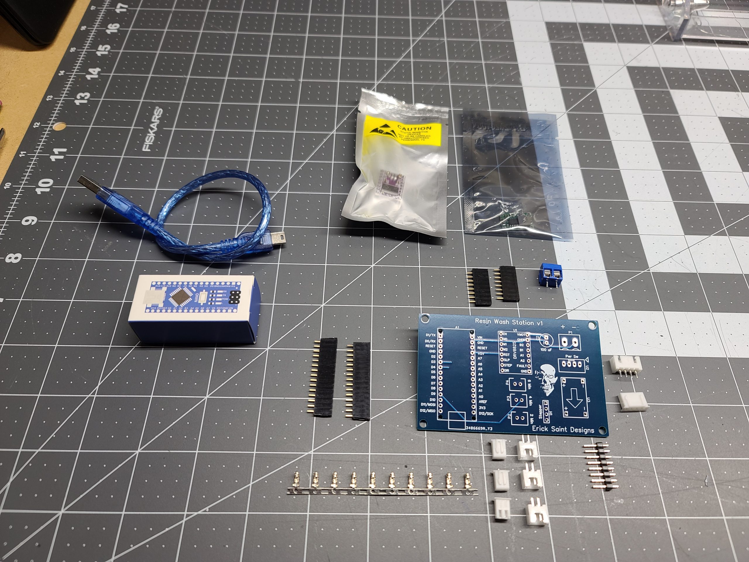
I will have a kit available for the remaining boards I have. There is one board error, as this was the first version, it’s easily fixable with a cut trace and a jumper. There is a pic in the electronics section that shows the repair. If there is enough demand for kits I will have a version two printed with the proper fix and maybe a slight layout change.
BOX AND BRACKETS
The gray box I have based this off of is just an off the shelf electrical box from Home Depot. I designed a new top because I thought I would need a thinner plastic layer for the magnetic coupling to work on the first design. Honestly I haven’t tried it with the original top, but I would try it before you spend the time printing the new cover. If your magnets are strong enough you might not need the new one, just adjust the spacing of your armature magnets to be as close to the cover as you can without rubbing.
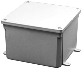
I designed all the printed parts for this in Fusion 360. I’ll include the STEP files below in the downloads section.


ELECTRONICS
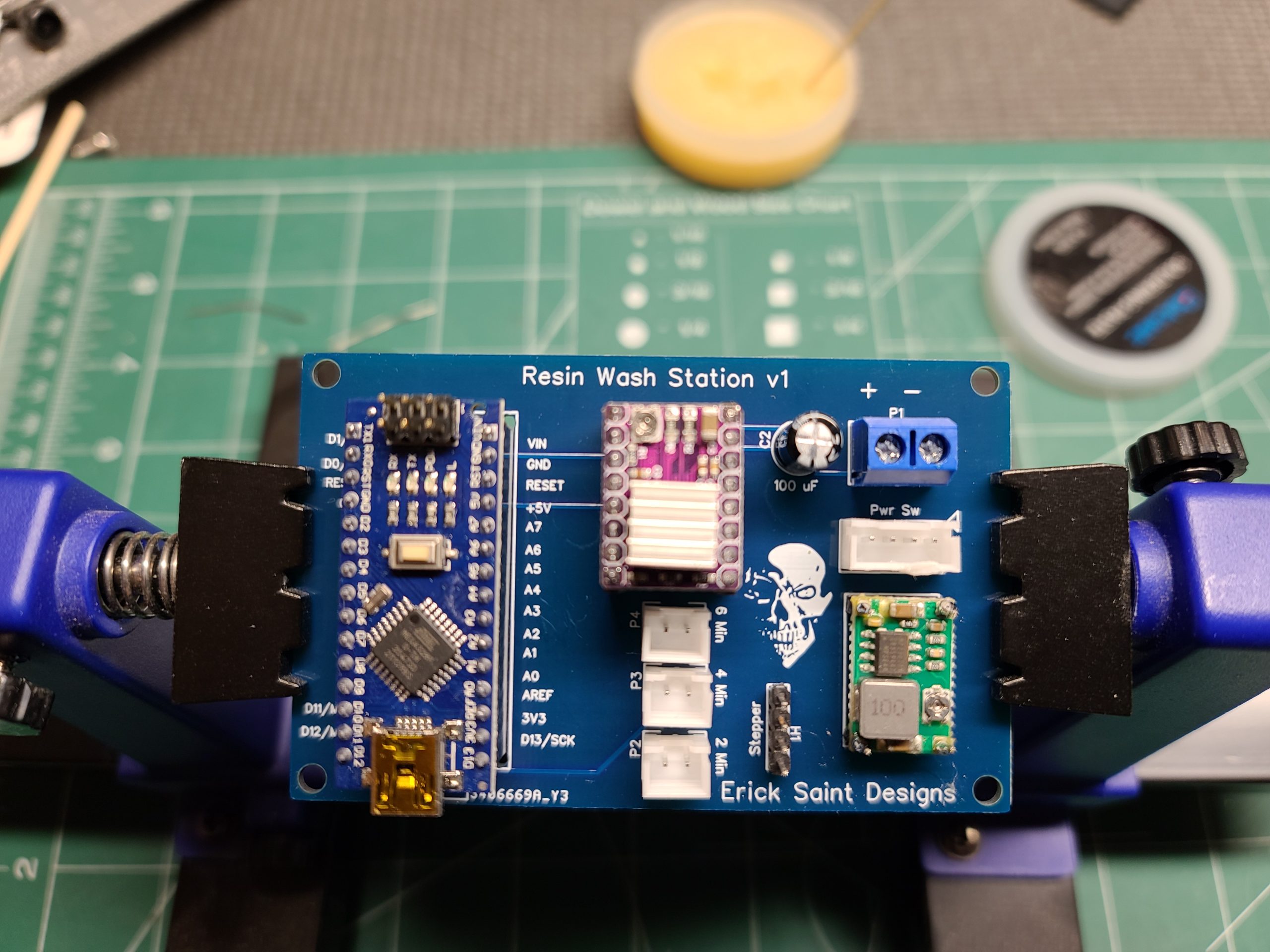
I ended up mounting the board upside down so that if I ever wanted to change the arduino code I would just have to remove the cover and plug into the nano. I will probably change board layout if there is a future version of this going forward. All switches, both latching power and momentary contact for the timed cycles, are wired using JST-XH connectors. A special crimper is needed for these connections, so if you don’t have them, you could solder your switches direct to the board.
The unit is powered by a 12V 5A power supply, this is enough to power the stepper at the speed it needs to turn to provide the vortex in the tank. The 12V is fed to an adjustable drop down converter, I’m outputting around 8V. WARNING: WHILE THE NANO CAN TAKE UP TO A 7-12V SOURCE ON PAPER, IT’S SUGGESTED TO INPUT CLOSER TO 7. I RECOMMEND ADJUSTING VOLTAGE OF THE CONVERTER BEFORE YOU PLUG IN THE NANO.
The stepper used is a basic NEMA 17 series. Depending on the motor you use, you may need to change your pin locations on the motor to get the proper locations to work. If you get the same motor I list in the parts section it should be plug and play. There is adjustment on the DRV8825 driver board for current limiting, make sure you set this according to the needs of your stepper. If you DIY this from scratch other driver boards can also have this setting.



GENERAL NOTES
- There were a few issues with v1 of the impeller, so I redesigned. I will post a video of the problems in a separate post on this page.
- The impeller STL in the download zip is redesigned for imbedded magnets, 3x18mm magnets used on both impeller and armature, I got these from Ace Hardware. The redesign also includes a plug for the bearing cavity, so it will print with no support junk to dig out of the hollow. But make sure you use support blockers where the magnets will go, ask me how I know. In Cura you can pause at a specific layer, in my case it was 22, to imbed the magnets. You will want to verify the layer needed to pause in your slicer preview. I printed with tree supports for just the bottom of the impeller post, there is a concave spot there because most plastic buckets have a little dimple in the bottom center. The concave makes it so you don’t have to sand down that dimple. The original design was giving problems with the magnets coming out even after trying to glue them in with resin, CA and epoxy. Due to the flexing in v1, I’m going to try printing the next version of the impeller solid, the first try was 5 or 10% gyroid and the arms flexed. Using 999 walls instead of 100% infill seems to give a stronger print overall, so we’ll see what happens. I have a feeling the PLA may still soften up and be a problem.
- Make sure when you set your magnets that they are offsetting poles.
- The included schematic is corrected, so the board problem above shouldn’t be an issue if you decide to DIY your own homebrew board from the schematic using the included arduino sketch.
- Depending on your 3d printer and your parts, you may have to adjust tolerances. The center post was designed using a cheap metal 608 bearing, but when I got the ceramic I needed to sand the post down because it was a hair smaller.
- Center post is just glued to the bottom of the bucket wit CA glue, but I did have to scuff it up with some 80 grit to get the glue to hold.
PARTS LIST
These parts may be bulk packs but it’s often cheaper to buy that way. A lot of these parts I had on hand, from other projects, so I worked them into this design. I used a ceramic bearing, because in testing, even a few hours in water was making the cheap 608 bearings rust.
- NEMA 17 Stepper
- Stepper Driver Board
- Latching Power Switch
- Momentary Push Button Switches
- Power Jack
- Power Supply
- Step Down Converter
- JST-XH Connectors
- Screw Terminals
- Ceramic 608 Bearing
DOWNLOADS



You must be logged in to post a comment.